EEPROM INTERFACING WITH PIC
The EEPROM is the permanent storage devices and can be erased and reprogrammed whenever we need. The data storing and retrieving from any EEPROM memory is very simple compared to other kind of memories.
Synopsis

The EEPROM (ELECTRICALLY ERASABLE PROGRAMMABLE READ ONLY MEMORY) is a very useful memory which can be used for storing data. The data storing and retrieving from any EEPROM memory is very simple compared to other kind of memories. As the name suggest the memory is electrically programmable and hence the data will be sustained in the memory until it is electrically erased or reprogrammed.

The EEPROM is the permanent storage devices and can be erased and reprogrammed whenever we need. These are the kinds of nonvolatile storage chip means when power is removed the content of the memory remains intact. It has no impact of power failure.

There are lots of EEPROM chips available most of them are easy to interface with a microcontroller. It would be even better if the microcontroller itself has a built-in EEPROM. The microcontroller used in this project is PIC18F4550 and it also has an inbuilt EEPROM memory other than the flash memory. The data can be easily stored into or retrieve using simple codes.

Description

The 24XXX series serial EEPROMs from the Technology support a bidirectional, 2-wire bus and data transmission protocol. The bus is controlled by the PIC18F4550 microcontroller (master), which generates the Serial Clock (SCL), controls the bus access and generates the Start and Stop conditions, while the 24XXX serial EEPROM works as slave. The 24XXX serial EEPROMs are I2C™ compatible and have maximum clock frequencies ranging from 100 kHz to 1 MHz


A0-A2 : Address inputs

SDA : Serial Data

SCL : Serial clock input pin

WP : Write Protect

GND : Ground

VCC : Supply

The project mainly has two parts, a serial communication part and EEPROM accessing part. The data which should be written into the EEPROM is received from the serial port. The internal hardware module USART is used for this purpose. The data which is read from the EEPROM is also send back to the serial port using the same hardware module.


Introduction to I2C:
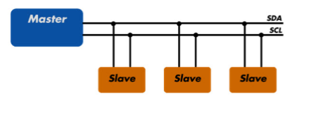
The I2C (Inter-Integrated Circuit) bus is a 2-wire serial bus which provides a small networking system for circuits sharing a common bus. The devices on the bus can vary from PIC18F4550 microcontrollers to LCD drivers to E2PROMs.

Two bi-directional lines, a serial data (SDA) and a serial clock (SCL) line, transmit data between the devices connected to the bus. Each device has a unique Address to differentiate it from the other devices on the bus, and each is configured either as a master or a slave when performing data transfers. A master is the device which initiates a data transfer and generates.


The clock signals necessary for the transfer. Any device that is addressed is considered a slave. The I2C bus is a multi-master bus, which means that more than one device that is capable of controlling the bus can be connected to it. Each transmission on the bus begins with the Master sending a Start condition and ends with a Stop condition. The Master then sends the address of the particular slave device it is requesting.

I2C terminology

Transmitter: This is the device that transmits data to the bus

Receiver: This is the device that receives data from the bus

Master: This is the device that generates clock, starts communication, sends I2C commands and stops communication

Slave: This is the device that listens to the bus and is addressed by the master

Multi-master: I2C can have more than one master and each can send commands

Arbitration: A process to determine which of the masters on the bus can use it when more masters need to use the bus

Synchronization: A process to synchronize clocks of two or more devices


The first four bits of this slave address are fixed as 1010. The next three bits specify a combination of the device address bit(s) and which 2K array of the memory is being addressed. The last bit of the slave address specifies whether a read or write operation is to be performed.


When this bit is a “1”, a read operation is performed, and when it is a “0”, a write operation is performed. After the Master sends a Start condition, the slave (E2PROM) monitors the bus and responds with an acknowledge when its address matches the transmitted slave address (see above Figure). The device then performs a read or writes operation depending on the state of the R/W bit.

Application

• 2-wire serial interface bus, I2C compatible

• EEPROM densities from 128 bits to 512 Kbits

• Bus speed from 100 kHz to 1 MHz

• Voltage range from 1.7V to 5.5V

• Low power operation

• Temperature range from -40°C to +125°C

• Over 1,000,000 erase/write cycles

• Up to 8 devices may be connected to same bus

Proteus design for EEPROM interfacing with PIC


Orcad design for RTC interfacing with PIC


EEPROM interfacing with PIC

/*  Name     : eprom.c
 *  Purpose  : Source code for Serial EEPROM AT24C02 with PIC18F4550.
 *  Author   : Gemicates
 *  Date     : 2017-07-06
 *  Website  : www.gemicates.org
 *  Revision : None
 */
 
                                          // Program to interface Serial EEPROM AT24C02 with PIC18F4550 microcontroller 
#include <htc.h>                          // Header file for PIC18F4550 series
#define _XTAL_FREQ 12000000               // 12MHz Crystal Frequency for PIC18F4550


                                          // register declaration
#define sda PORTBbits.RB0                 // To assign RB0 bit in PORTB as Serial data pin for 24C02C EEPROM
#define scl PORTBbits.RB1                 // To assign RB1 bit in PORTB as Serial Clock pin for 24C02C EEPROM
#define SW1 PORTBbits.RB2                 // To assign RB2 bit in PORTB as input
#define SW2 PORTBbits.RB3                 // To assign RB3 bit in PORTB as input 
#define SW3 PORTBbits.RB4                 // To assign RB4 bit in PORTB as input
#define SW4 PORTBbits.RB5                 // To assign RB5 bit in PORTB as input
#define rs  PORTCbits.RC0                 // To assign RC0 bit in PORTC as register select pin
#define rw  PORTCbits.RC1                 // To assign RC1 bit in PORTC as read write pin
#define en  PORTCbits.RC2                 // To assign RC2 bit in PORTC as enable pin
#define led PORTCbits.RC4                 // To assign RC4 bit in PORTC as led output pin
#define led1 PORTCbits.RC5                // To assign RC5 bit in PORTC as led1 output pin
#define lcd_data_pin PORTD                // To assign PORTD as output
#define output PORTA                      // To assign PORTA as output

                                          // Function declarations
void send_byte(unsigned char value);
void lcd_command (unsigned char comm);
void lcd_data(unsigned char disp);

bit ack;
unsigned char reead,write,write2,i,j,k;
unsigned int temp;

void lcd_command(unsigned char comm)       // Function to send command to LCD
{
        lcd_data_pin=comm;
        en=1;
        rs=0;
        rw=0;
        __delay_ms(30);
        en=0;
}
void lcd_data(unsigned char disp)          // Function to send data to LCD
{
        lcd_data_pin=disp;
        en=1;
        rs=1;
        rw=0;
        __delay_ms(30);
        en=0;
}
void lcd_dataa(unsigned char *disp)        // Function to send string on LCD
{
        int x;
        for(x=0;disp[x]!=0;x++)
        {
                lcd_data(disp[x]);
        }
}
void lcd_ini()                             // Funtion to Initialize LCD
{
        lcd_command(0x38);                 // for using 8-bit 2 row LCD
        __delay_ms(30);
        lcd_command(0x0F);                 // for display on, cursor blinking
        __delay_ms(30);
        lcd_command(0x80);                 // to set cursor at 1st position of 1st row of LCD.
        __delay_ms(30);
}
void aknowledge()                          // acknowledge condition
{
        scl=1;
        __delay_ms(30);
        __delay_ms(30);
        scl=0;
}
void start()                               // start condition
{
        sda=1;
        scl=1;
        sda=0;
        scl=0;
}
void stop()                                // stop condition
{
        sda=0;
        scl=1;
        sda=1;
        scl=0;
}
void send_byte(unsigned char value)        // send byte serially
{
        unsigned int i;
        unsigned char send;
        send=value;
        for(i=0;i<8;i++)
        {
                sda=send/128;              // extracting MSB
                send=send<<1;              // shiftng left
                scl=1;
                scl=0;
        }
   ack=sda;                                // reading acknowledge
   sda=0;
}
unsigned char read_byte()                  // reading from EEPROM serially
{
        unsigned int i;
        sda=1;
        reead=0;
        for(i=0;i<8;i++)
        {
                reead=reead<<1;
                scl=1;
                if(sda==1)
                        reead++;
                scl=0;
        }
        sda=0;
        return reead;                       // Returns 8 bit data here
}
void Save()                                 // save in EEPROM
{
        start();
        send_byte(0xA0);                    // device address
        aknowledge();
        send_byte(0x0000);                  // word address
        aknowledge();
        send_byte('G');                     // send data
        aknowledge();                       // send aknowledgement for data
        send_byte('E');
		aknowledge();
        send_byte('M');
		aknowledge();
        send_byte('I');                     // send data
        aknowledge();
        send_byte('C');
		aknowledge();
        send_byte('A');
        aknowledge();
	    send_byte('T');                 // send data
        aknowledge();
        send_byte('E');
		aknowledge();
        send_byte('S');
        aknowledge();
        stop();
        if(ack==0)
        {
                led=0;
                __delay_ms(30);             // delay function of 30ms
                lcd_command(0x86);          // To display the data on  6th position in 1st row
                lcd_data('G');
                lcd_command(0x87);          // To display the data on  7th position in 1st row
                lcd_data('E');
		lcd_command(0x88);          // To display the data on  8th position in 1st row
                lcd_data('M');
                lcd_command(0x89);          // To display the data on  9th position in 1st row
                lcd_data('I');
		lcd_command(0x8A);          // To display the data on  10th position in 1st row
                lcd_data('C');
                lcd_command(0x8B);          // To display the data on  11th position in 1st row
                lcd_data('A');
		lcd_command(0x8C);          // To display the data on  12th position in 1st row
                lcd_data('T');
		lcd_command(0x8D);          // To display the data on  13th position in 1st row
                lcd_data('E');
                lcd_command (0x8E);         // To display the data on  14th position in 1st row
                lcd_data('S');
		led=1;
                __delay_ms(30);
        }
        else
        led1=0;
		aknowledge();


void Read()                                 // Function of read the data
{
        start();
        send_byte(0xA0);
        aknowledge();
        send_byte(0x0000);
        aknowledge();
        start();
        send_byte(0xA1);                    // device address
        aknowledge();
        i=read_byte();
        aknowledge();
        j=read_byte();
        aknowledge();
	k=read_byte();
        aknowledge();
        stop();
}

void Read_dep()
{
        start();
        send_byte(0xA0);
        aknowledge();
        send_byte(0x0003);
        aknowledge();
        start();
        send_byte(0xA1);                   // device address
        aknowledge();
        i=read_byte();
        aknowledge();
        j=read_byte();
        aknowledge();
	k=read_byte();
        aknowledge();
        stop();
}

void Read_session()
{
        start();
        send_byte(0xA0);
        aknowledge();
        send_byte(0x0006);
        aknowledge();
        start();
        send_byte(0xA1);                    // device address
        aknowledge();
        i=read_byte();
        aknowledge();
        j=read_byte();
        aknowledge();
	k=read_byte();
        aknowledge();
        stop();
}

void main()                                 // main function
{
		TRISD=0x00;	            // TRISD register as output
        TRISA=0x00;                         // TRISA register as output
        TRISC=0x00;                         // TRISC register as output
        TRISB=0x00;                         // TRISB register as output
        PORTD=0x00;                         // PORTD as output
        PORTA=0x00;                         // PORTA as output
        PORTC=0x00;                         // PORTC as output
        PORTB=0x00;                         // PORTB as output
        
        lcd_ini();
        lcd_dataa("Sent :");
        while(1)                            // Infinite loop
        {
					if(SW1==0)
					{
                                                 
										Save();
                                        
					}
					if(SW2==0)
					{
										led1=0;
										Read ();
										led1=1;
					}
					if(SW3==0)
					{
										led1=0;
										Read_dep();
										led1=1;
					}
					if(SW4==0)
					{
										led1=0;
										Read_session();
										led1=1;
					}
        }
                                            // return 0;
}

Error message here!

Show Error message here!


Forgot your password?

Error message here!

Send OTP

Error message here!

Show Error message here!


Lost your password? Please enter your email address. You will receive a password you Need.

Send Error message here!


Back to log-in

Close